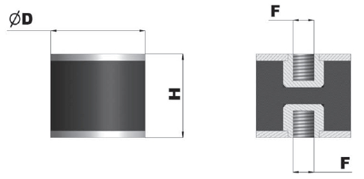
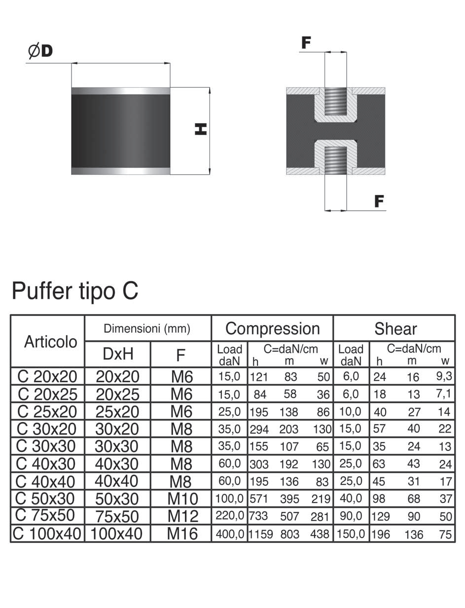
Puffer Typ C
|
Articolo Article Artikel |
Dimension |
Compression |
Shear |
|||||||
|
D x H (mm) |
F (mm) |
Load (daN) |
C = daN/cm |
Load (daN) |
C = daN/cm |
|||||
|
h |
m |
w |
h |
m |
w |
|||||
|
C 20x20 |
20x20 |
M6 |
15 |
121 |
83 |
50 |
6 |
24 |
16 |
9,3 |
|
C 20x25 |
20x25 |
M6 |
15 |
84 |
58 |
36 |
6 |
18 |
13 |
7,1 |
|
C 25x20 |
25x20 |
M6 |
25 |
195 |
138 |
86 |
10 |
40 |
27 |
14 |
|
C 30x20 |
30x20 |
M8 |
35 |
294 |
203 |
130 |
15 |
57 |
40 |
22 |
|
C 30x30 |
30x30 |
M8 |
35 |
155 |
107 |
65 |
15 |
35 |
24 |
13 |
|
C 40x30 |
40x30 |
M8 |
60 |
303 |
192 |
130 |
25 |
63 |
43 |
24 |
|
C 40x40 |
40x40 |
M8 |
60 |
195 |
136 |
83 |
25 |
45 |
31 |
17 |
|
C 50x30 |
50x30 |
M10 |
100 |
571 |
395 |
219 |
40 |
98 |
68 |
37 |
|
C 75x50 |
75x50 |
M12 |
220 |
733 |
507 |
281 |
90 |
129 |
90 |
50 |
|
C 100x40 |
100x40 |
M16 |
400 |
1159 |
803 |
438 |
150 |
196 |
136 |
75 |
![]() Zur Vergrößerung auf das Bild klicken
Zur Vergrößerung auf das Bild klicken


General precautions to be followed in the installation and assembly of load cells: